BrewPi Soldering Guide
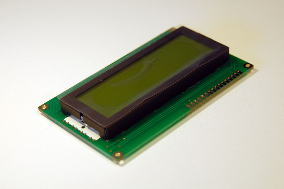
Get your LCD.
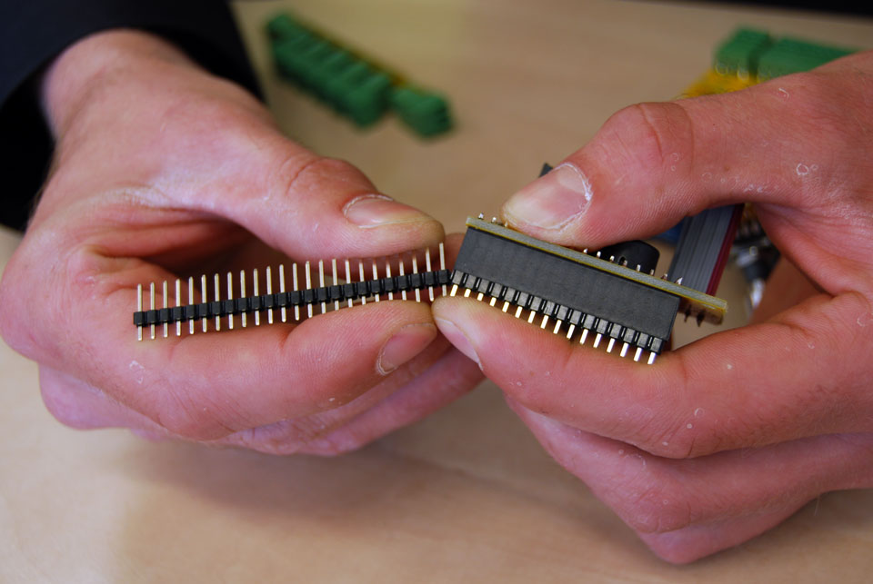
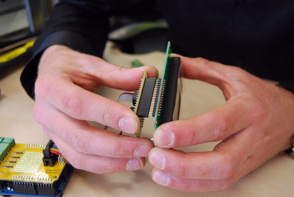
You got a 40pin header with the kit, so you will have to break off 16 pins. A reliable way of doing this is inserting the connector in the female header and applying force like in this picture, while keeping pressure on the last pin in the header.
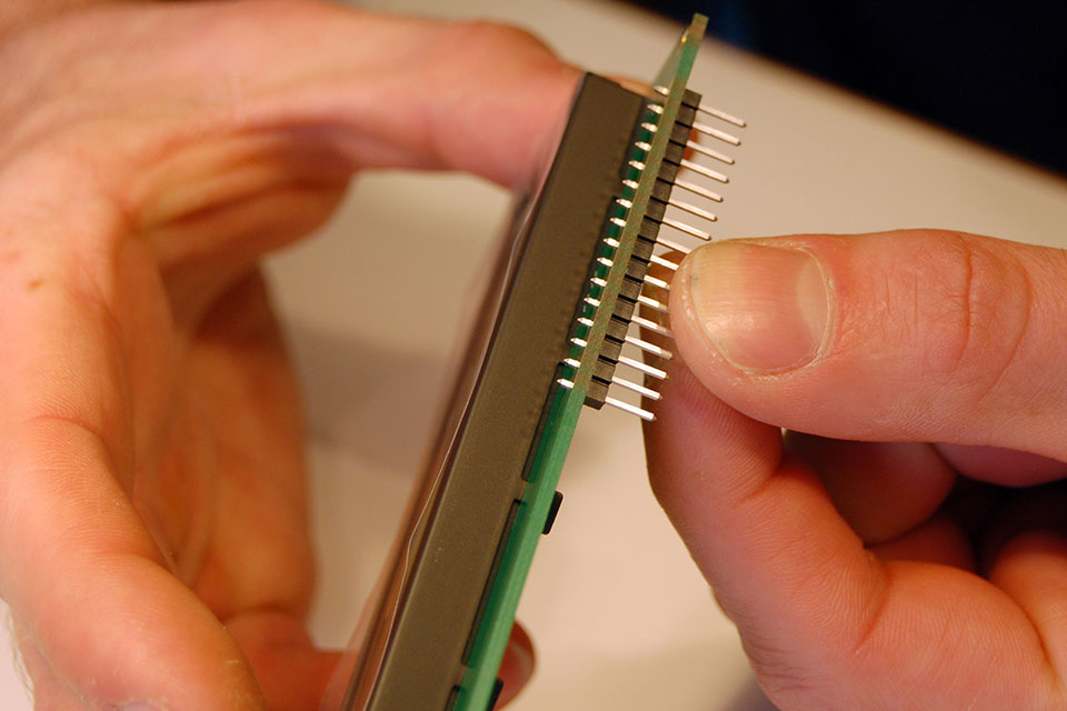
Insert the male header from the bottom and like before, solder the middle pin first. Then check alignment.
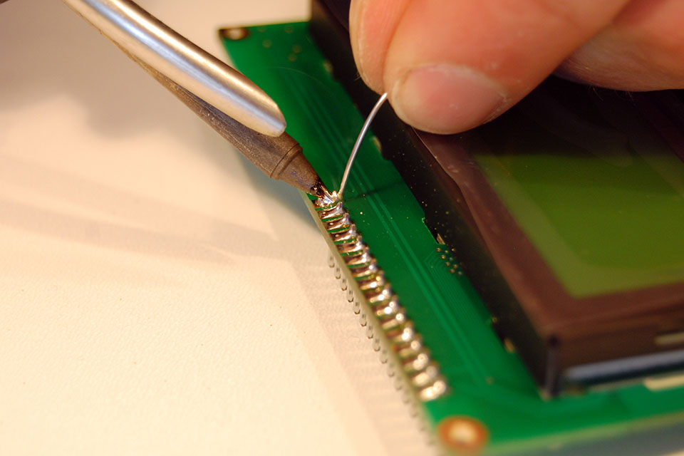
Finish soldering the rest of the pins. I get the best result by pressing the tip against the pin and applying solder from the other side. When it flows, drag your tip off the pad.
You can now plug the LCD backpack onto your LCD.
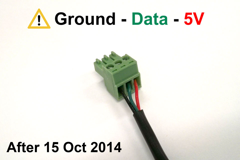
The new high temperature proof temperature sensors already have soldered ends, you can skip the next steps. Please also see the case assembly guide. After October 15, 2014, the sensors have Red=5V, Green=DATA, Black=GND.
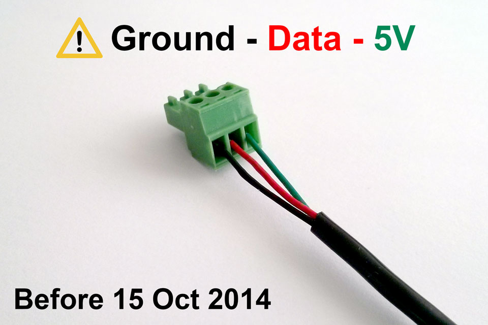
Before October 15, 2014, the RED wire was used for data! Pay attention to when you got your sensors.
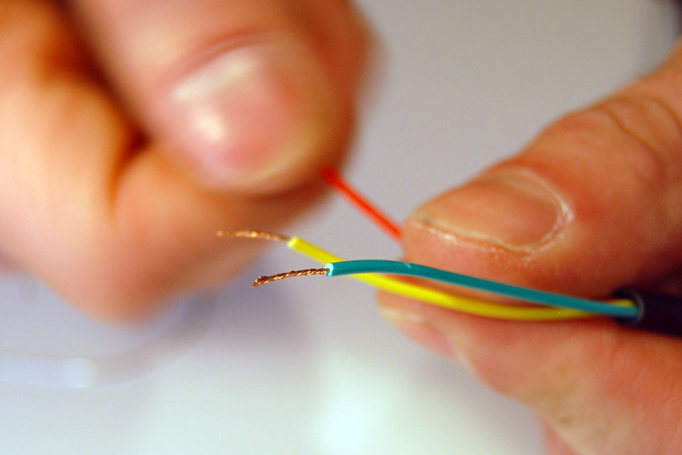
It is a good idea to make some neat ends on your temperature sensors. Start by twisting the wires.
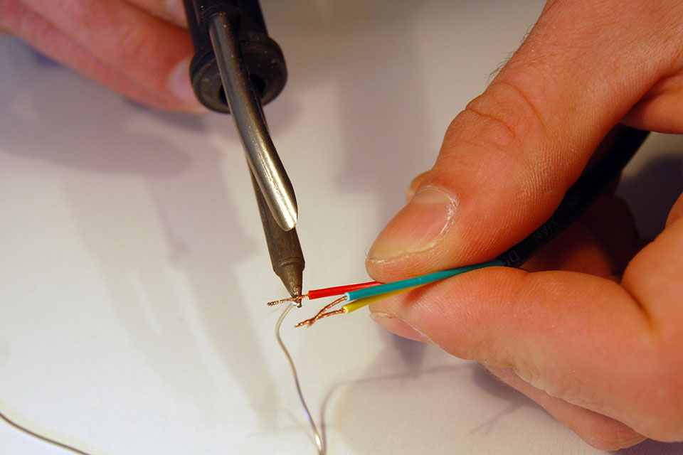
Next, heat the wire and add some solder until the wire absorbs it.
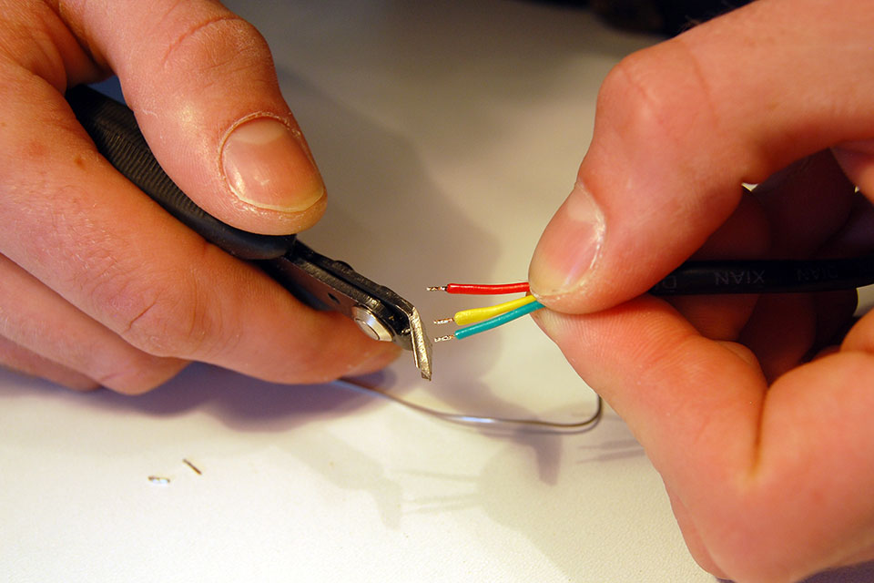
Cut off most of the wire so you have about 2mm left.
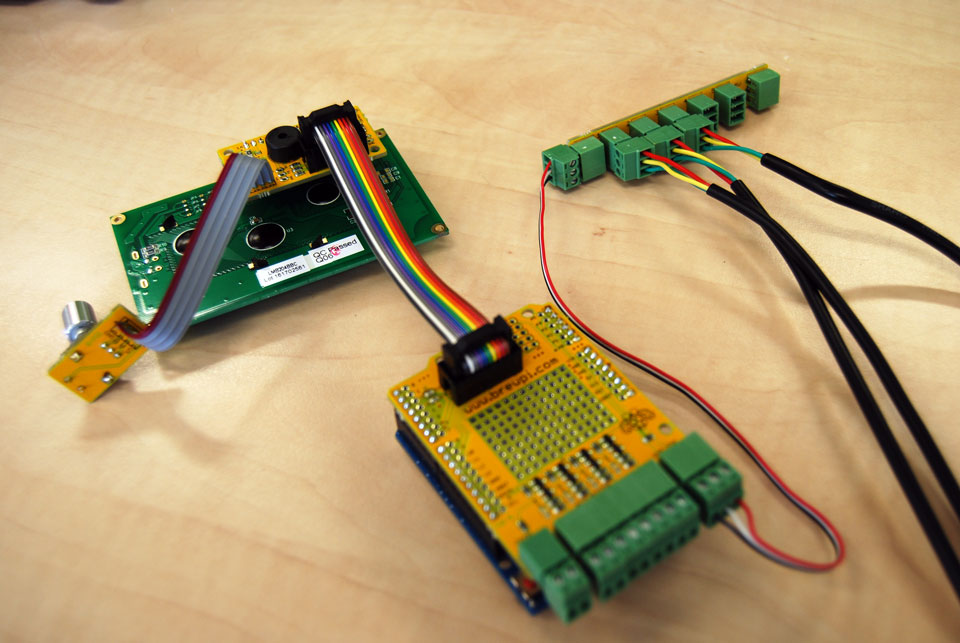
Next, use a small screwdriver to connect the plugs to your sensors.
ATTENTION: This solder guide was made with older temperature sensors. If your sensors have black, red, green wires: refer to the image above. If you sensors have red, green, yellow wires, then red = data. If they don’t work, try swapping ground and data.
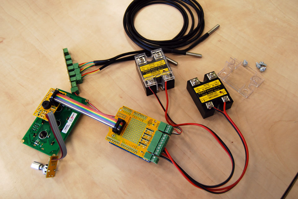
Do the same for your SSRs. The first actuator output has a blue LED, so use that one for cooling. The SSR side with the LED should be connected to your Arduino. The other side should interrupt ONE of the leads to your compressor/heater.
The leftmost 2pin terminal is for a door switch. If you connect it to your fridge door switch (disconnect it from mains!) BrewPi will know when the door is open. It can log that and turn on a light for you.
Thats it! You are ready to start using BrewPi!