BrewPi Arduino shield soldering guide for Rev A
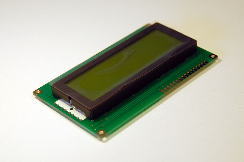
Get your LCD.
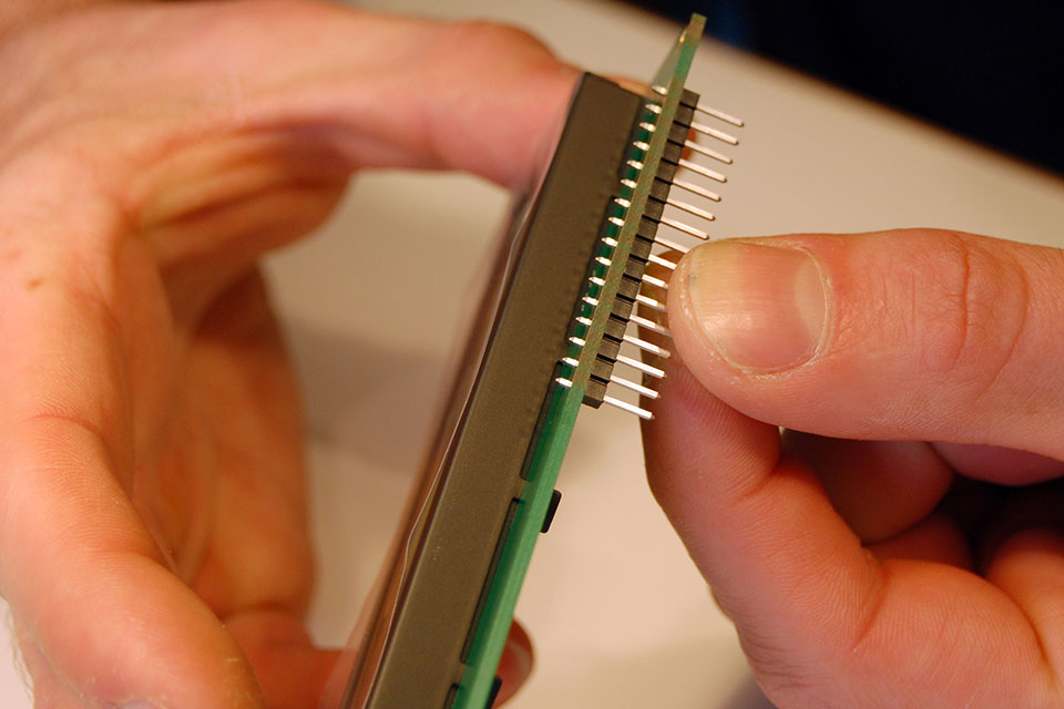
Insert the 16p male header from the bottom and like before, solder the middle pin first. Then check alignment.
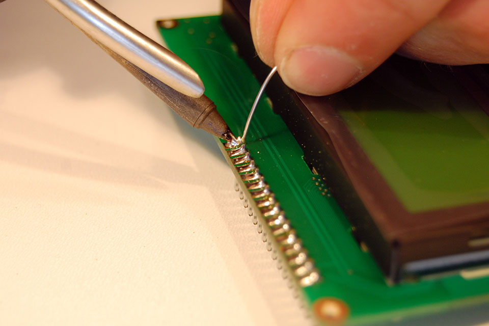
Finish soldering the rest of the pins. I get the best result by pressing the tip against the pin and applying solder from the other side. When it flows, drag your tip off the pad.
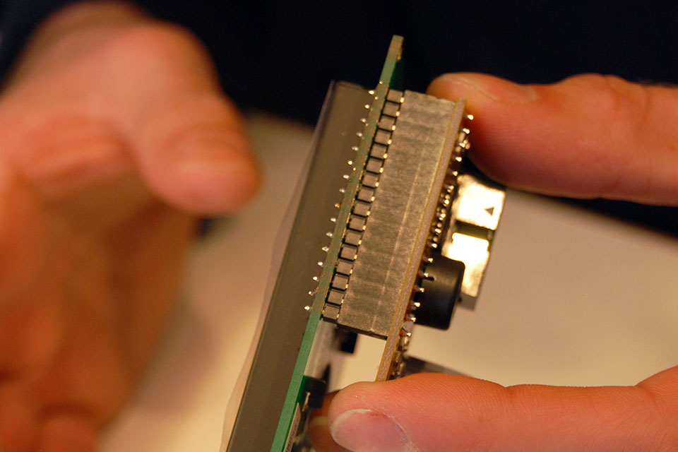
Now you can plug your backpack onto your LCD.
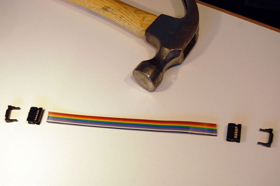
Time to assemble the flat cable.
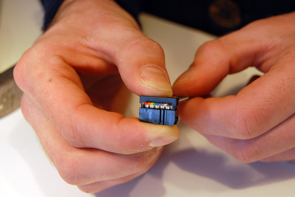
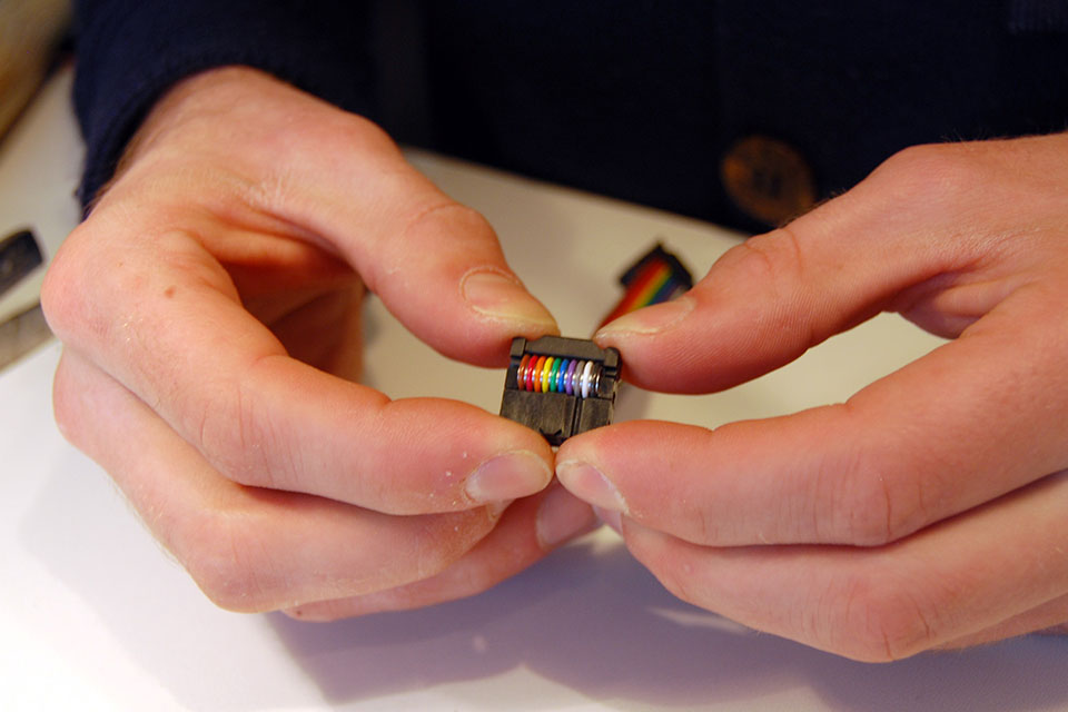
The black side of the cable should go at the side of the pin 1 marking on both sides. This means that the key will point inwards on one side and outwards on the other side. Push the teeth through the cable with a hard flat object until the parts touch.
The connectors should be assembled in this orientation. If you made a mistake or want to change the length of your cable, you can pry the connectors off again, cut off the used bit and push them into your shorter cable.

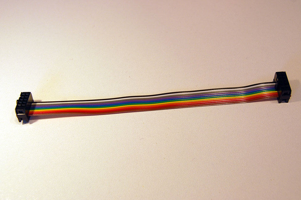
When both sides are done, fold the cable over the connector and insert the strain relief clips.
The strain relief clip is easy to insert, just press it down.
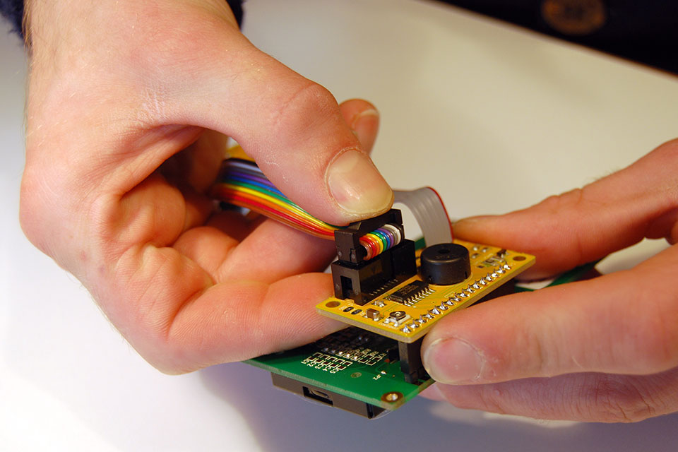
Insert your brand new cable into the LCD backpack…
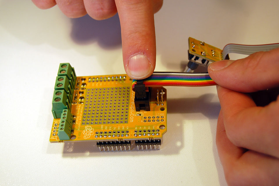
…and into the main shield.
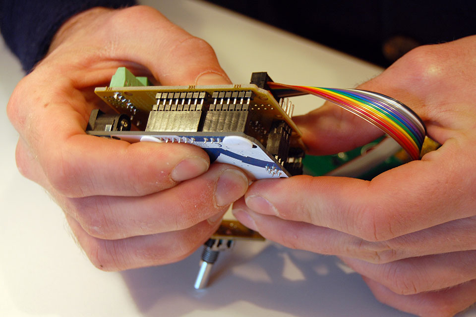
Now put the assembled shield back onto your Arduino.
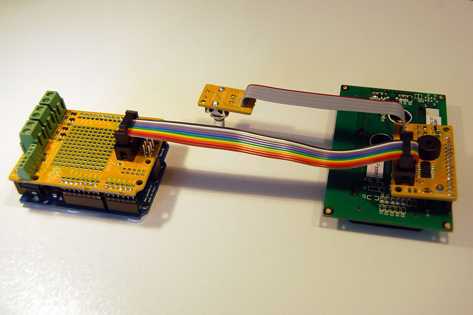
All done! It is a good idea to check your board for solder shorts now and if you have a multimeter, make sure there is no short between power and ground. The next page shows how to connect the SSRs, sensors and Raspberry Pi.
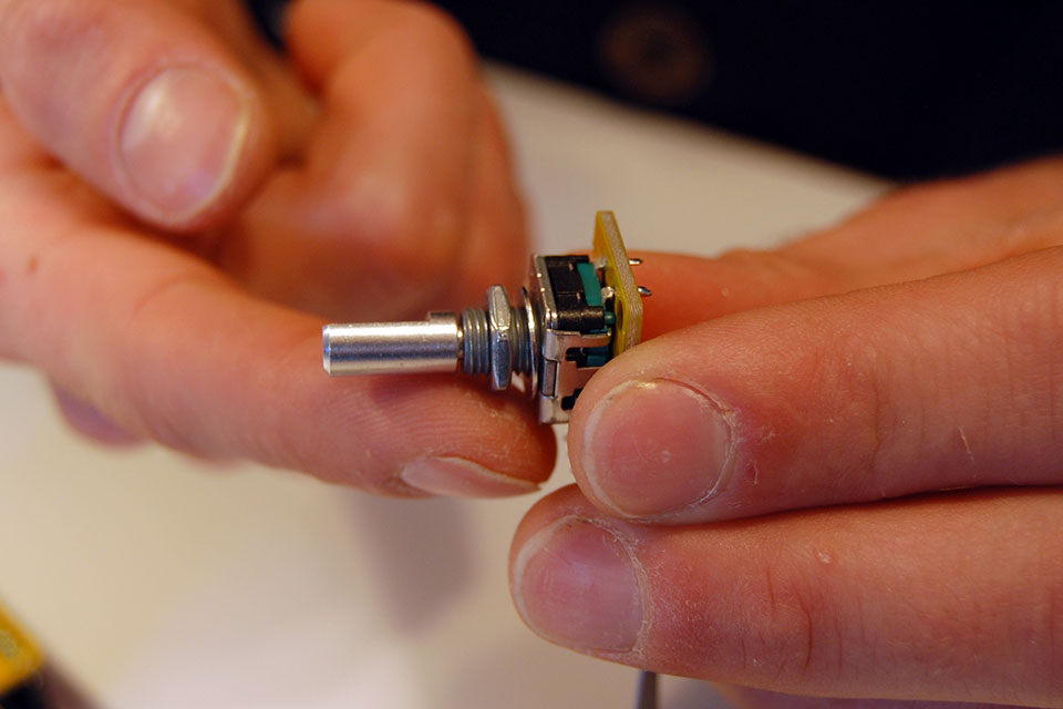
Screwing the nut and the spacer onto the rotary encoder is a good way to avoid losing it before you mount it through a panel.
15 Comments
Leave a Comment
You must be logged in to post a comment.
The bottom of page 1,
“This picture is just to show you what good solder joints look like: shiny, concave and covering the whole pad. We will get to this board later.”
I think you mean convex 🙂
I can’t wait to get my hands on one of these units, loving following the progress!
No I am pretty sure I mean concave…
I quote from this guide:
The whole of the joint itself is a convex structure COD yes, but in the way Elco uses it here it makes sense. They’re talking about the cross sectional profile of the joint in which case it’s convex. If it were concave it would look bulbous like a mushroom. I too for a moment thought hrmm…concave you say until I considered this interpretation.
Boy I really buggered that up and swapped some of the terms. The joint stands off the board = convex, but here the term concave describes the profile of the joint. If it were convex it would be a bulbous ball…the characteristic of a cold solder joint.
I’ll second concave as correct.
smooth volcano shape 🙂
Nice setup ! I`m currently making it … just had to buy a SD card big enough for all the setup. My 4GB was to small. 8GB seems to be ok.
ugh, i soldered the ICP header on the LCD board on the wrong side, and my solder sucker is stuck 🙁 ah well
Been there myself… Any attempt to get it off will probably ruin the connector, so you will have to buy another one. Luckily they are very common. To get it off, you can also make the pin side one big blob of solder, so you can heat all 10 at once.
You could leave it and assemble the cable in a way that works I think, but it will be very high.
Yeah i figured i could just flip the connector and try to bend the header for the LCD to allow for some room to the connector, that or break off some of the plastic around the header and solder wires to the pins and just create a connector out of it that doesnt require so much height.
Use a heat gun. Heat it carfully up and give it a little “hit” to the edge of something. With a little practice you can get it out from there. If you use it too much, you will ruin your print… For emergency use only.
Dont have a heat gun and im not too keen on ruining the print, im going to try something tommorow and evalute after that.
If you have the new Rev C board, note these instructions are still for the Rev A shield. Elco says the new instructions will be coming soon, but to help folks in the meantime, a few differences to note:
– There are more pieces in the parts bag – instead of soldering the screw posts to the board as pictured, now you solder terminals and the screwpost plugs will attach to the sensor/actuator wires.
– If you have an older Uno, there are fewer pins on the arduino than on the shield. Let them overhang the socket by the two pins.
– There is a 40 pin header in the kit. It’s for the 16 pin space in the LCD. Just cut to size, the extra is a bonus!
– and not pictured in these instructions is the one-wire distribution board. Self explanatory, once you look closely at it, although if you also got the case, I’m still not quite sure what to do with the one-wire piece of the case kit. But that’s a different matter.
Good luck!
What would be the major diffs between this post and the soldering of parts for revC shield?
I tried to outline the major differences in the comment just above yours.
Yes tanks I saw that a bit too late…
Any way with your comment and the various info from elco I managed to build everything.
Regarding the case I put the one wire hub on the top of the case at the back and its corresponding pcb on top of it.
It is convenient then to connect the hub to the one wire port of the arduino and to plug the thermal sensors into the hub.
Then with the dynaconfig branch everything can be set-up dynamically
So congrats to all the contributors, the job you have done is really impressive and the level of integration, testing capabilities and look & feel is really high!