BrewPi Soldering Guide
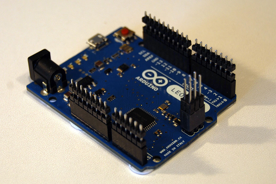
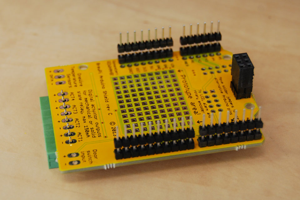
We will start by soldering the 5 Arduino headers. Insert them into your Arduino to hold them straight.
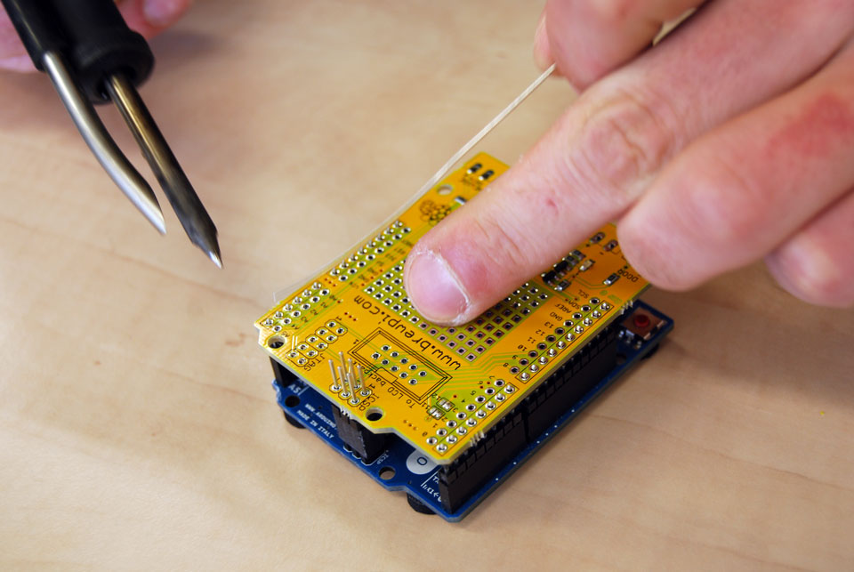
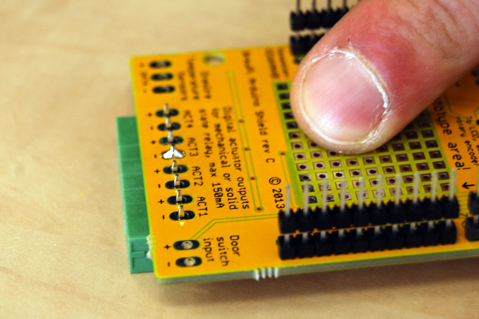
But the shield on the headers an press down firmly. Solder the 4 headers on the edges. If you are wondering what that weird thing on my soldering iron is: its a fume extractor. Keeps me from inhaling to much flux vapor while soldering.
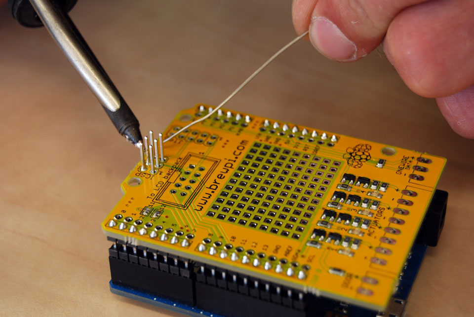
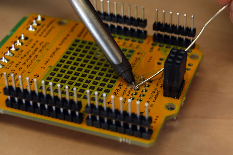
Do the 6 pin ICSP header last. Try to not get the pins full of solder and only solder the bottom. Remember: first heat, then solder.
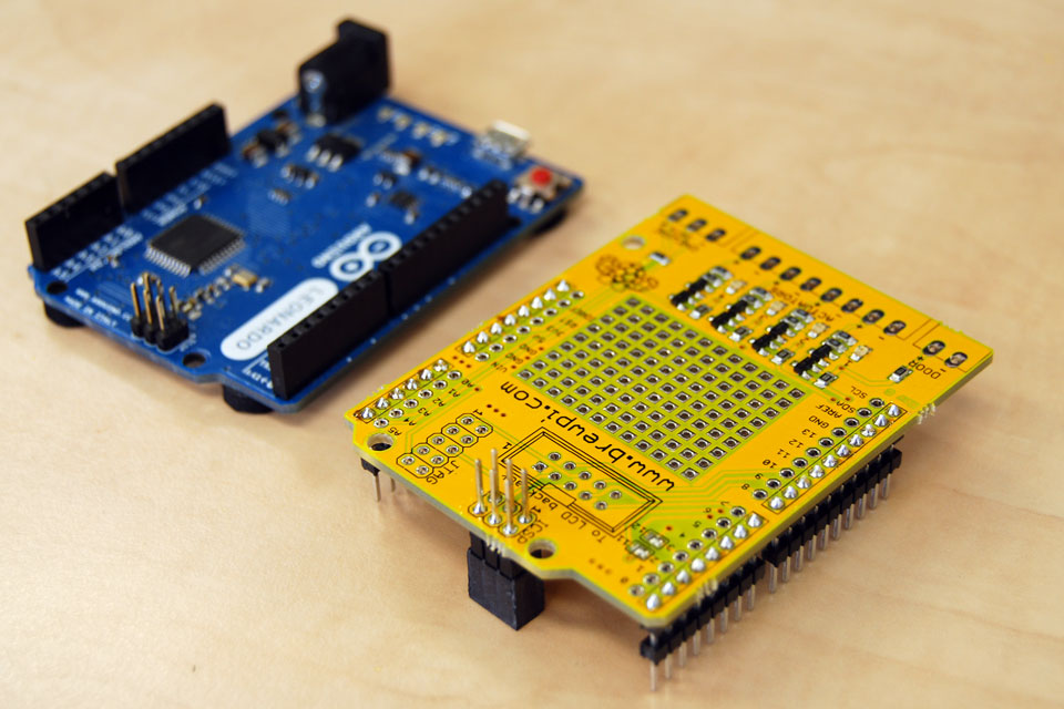
When you are done with the 5 headers, you can take the shield off the Arduino again.
Next are the green plug-able terminals. We’ll start with the biggest one.
On components with multiple pins, I recommend soldering only the middle pin first, then check the alignment before soldering the rest. Straightening the component is still easy with just one pin to reheat. Solder the rest when you are happy with the alignment.
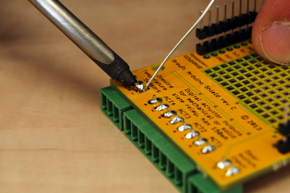
Solder the 2 pin door terminal and 3 pin OneWire terminal too.
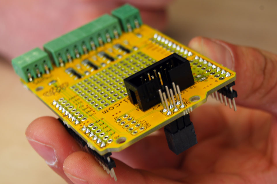
Last part on the main shield is the connector for the LCD backpack cable. Insert it with the opening towards the 6pin header.
Again, solder one pin first and then check if it is properly mounted before soldering the others.
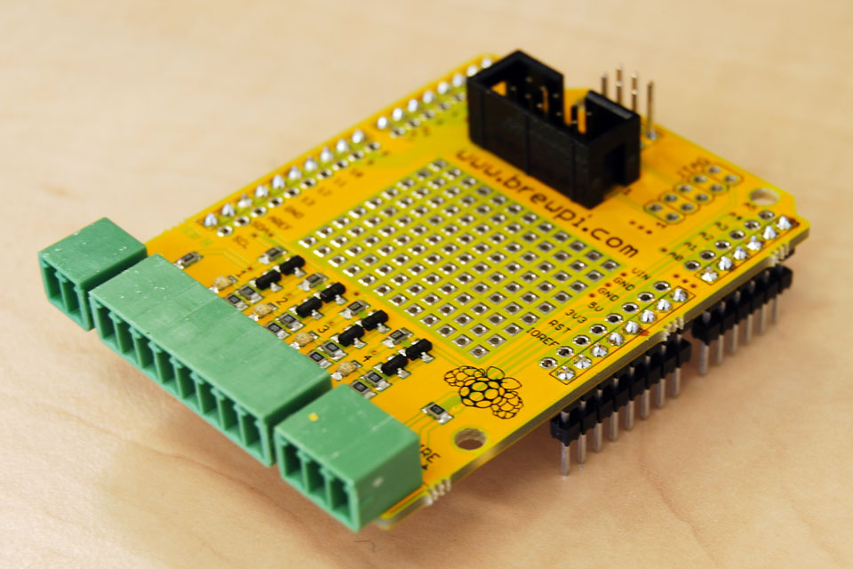
Main board done! Next is the LCD backpack.