BrewPi Spark V3: production progress
Hi Guys,
We’re getting closer to the release of the BrewPi Spark V3, but it has taken a bit longer than I originally planned. The BrewPi Spark V2 has been out of stock since March.
In this posts, I’d like to share some photos of the production process so you get an idea of what’s happening behind the scenes. I’m really excited about the improvements from V2 to V3, but in this blog posts I will not talk about new features. I’ll save that for the release, which I hope will be in about 2 weeks.
Electronics
We did a complete redesign of the electronics for the BrewPi Spark V3, to make it more robust and easier to manufacture. Some of the biggest changes are:
- We switched to the P1 instead of the Photon. The P1 is a module very similar to the photon, but designed to be directly soldered to the board. This also allows us choose a much more robust USB connector and to move the status LED to the front with a light pipe.
- A better and slightly bigger display.
- All connectors on top and bottom. And if you only need to connect 2 sensors and 2 actuators, you only need the bottom row.
So how are the electronics manufactured? All the electronics are assembled by eM.Be Electronics in the Netherlands.
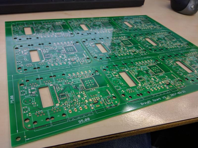
We start with a panel of bare PCBs, which are produced by Hackvana, which I highly recommend. You can find them on IRC: #hackvana on freenode.
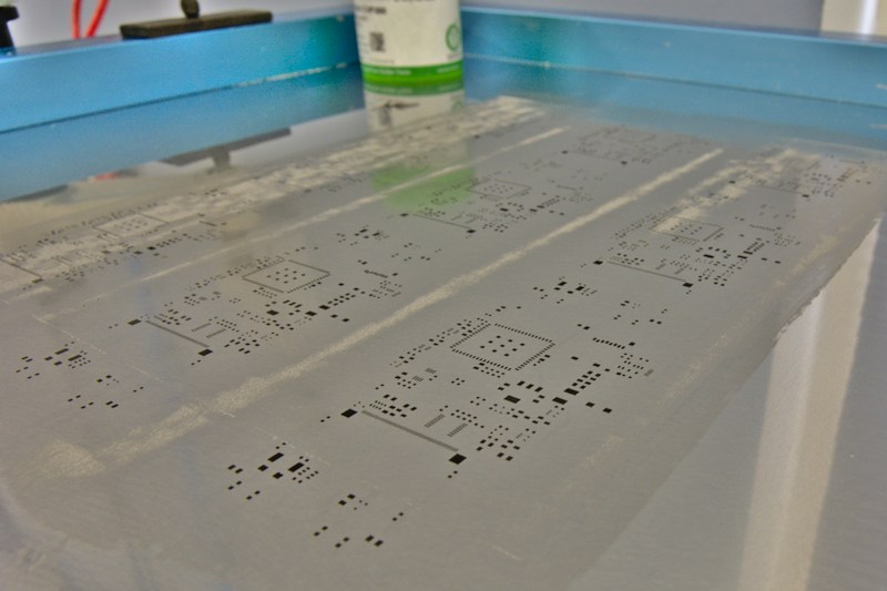
To apply solder paste for the surface mount components, a stencil is placed over the panel and paste is applied with a squeegy.
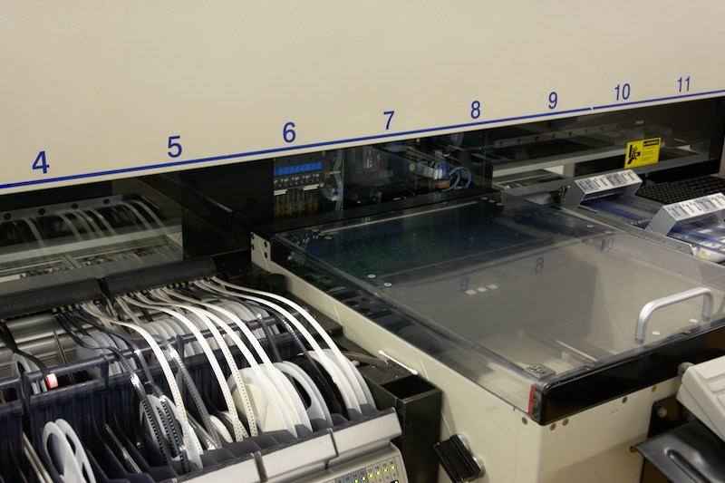
The board that just got it’s solder paste is placed into the pick-and-place machine which picks up all the surface mounted parts from multiple feeders and places them on the board. You can see it in action in the video below.
Next, the boards are placed in the vapor-phase reflow oven. This melts the solder paste and solders the components to the board.
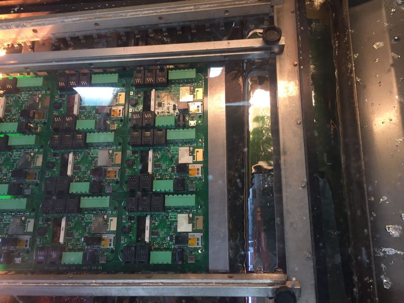
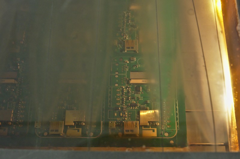
Finally, the through hole components (mostly connectors) are placed by hand and the board is then placed onto the belt of the wave soldering machine. On the right side of the photo, you can see this wave of molten solder. The board moves over this wave to solder all of the pins on the bottom.
Casing
The biggest change from the V2 to the V3 is that the V3 will have a beautiful enclosure. The Spark V2 enclosure was made by vacuum forming and CNC milling, which has low startup costs but is limited in precision and design freedom.
For the BrewPi Spark V3, we switched to injection moulding. Making the mould is very costly, but stamping out more units is cheap. As long is we sell many units, it will be worth the investment. With injection moulding, molten plastic is pushed into a mould at very high pressure. It solidifies and is released. Boom, next!
I have yet to receive the first injection moulded parts, so I cannot show you those yet. But I can show you how they are made.
The first step of course was 3D modeling the new enclosure. We worked with Frits Stam from Van Alles Wat Ontwerp. Frits is also an avid 3D printer, which was useful in testing early designs. Frits designed the new enclosure from scratch, based on a mood board, a 3D model of the electronics and technical specs.
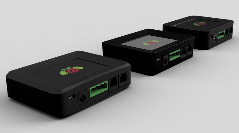
Frits Stam designed the new casing for us. Here are some of the earlier design studies he made to determine the direction to go.
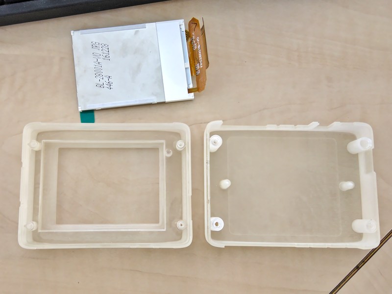
We 3D printed the enclosure to make sure it fitted well with the electronics before we started the expensive mould making process.
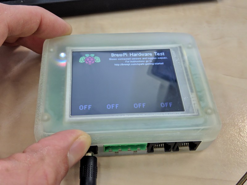
It fits! You can also see the new light pipe for the status LED in this photo. This prototype is printed in clear plastic, because it can be printed with higher precision. The final product will be black.
Now that the 3D design was finished, we could start with manufacturing the mould. We found a great partner in Mafa B.V..
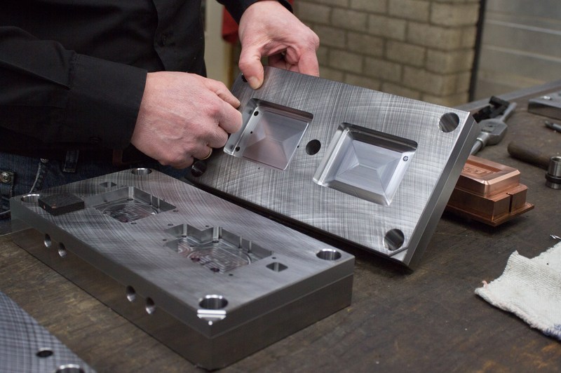
Here’s a photo of the injection mould at an early stage.
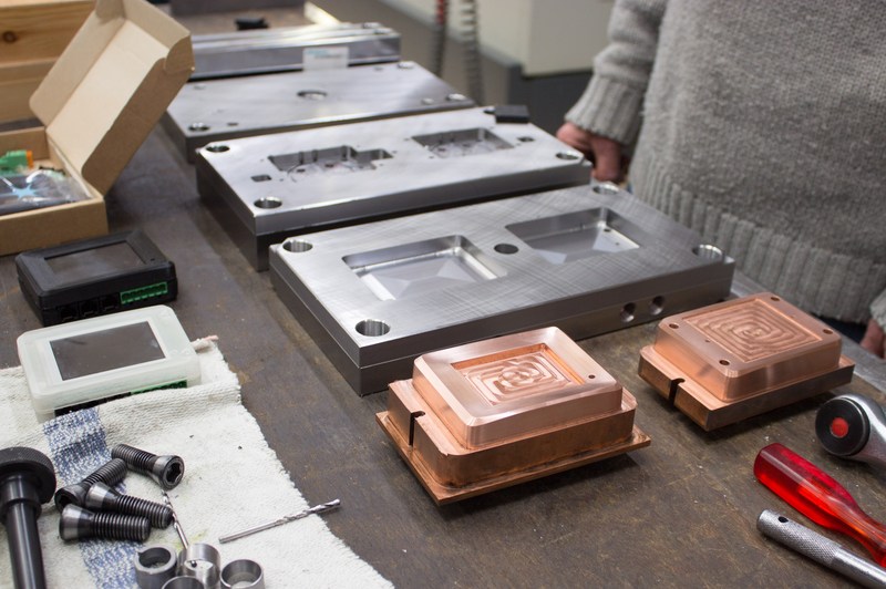
The copper parts at the front are not part of the mould. They are used to give the mould its surface finish. The copper parts are electrical probes for electrical discharge machining. They are held at very close distance to the mould until sparks cross the gap. The sparks erode the metal and create that typical surface finish you’ll find on almost all non-glossy plastic products.
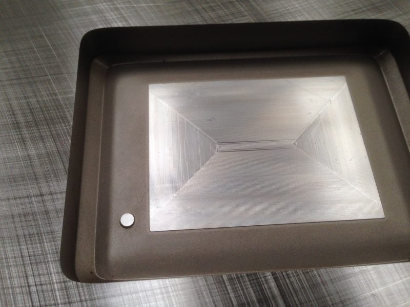
The surface finish resulting from the spark erosion process.
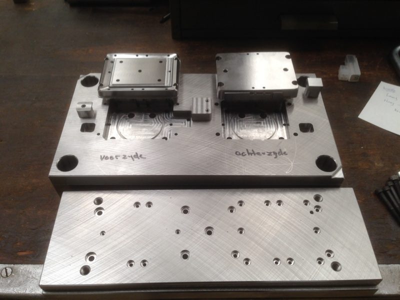
And these are the last photos I have from the injection mould. In this photo, you can see the inserts that are screwed into the outer shell to create a thin walled enclosure. You can also see the many holes for push pins, cooling water, and molten plastic.
That’s all for now! As you can see, the new BrewPi Sparks are almost ready. I will receive the first injection moulding tests next week. We probably need to do some minor tweaks and then we’re ready to open the store for BrewPi Spark orders again!
Cheers!
View all replies on our forum
10 more replies
Wow! Exciting stuff! Glad to see the project is moving forward, both on hardware and software. The casing looks great, can’t wait to break my v2!
Can’t wait Elco! So we can expect these for sale on June 12?
Looks GREAT!
You say that you are switching from the photon to the P1. Seems like the hardware is pretty similair. But just to be sure, will the “old” Spark v2 still be supported with new software and firmware?
Best of luck with the release!
How’s it looking for release date?
The injection mould had to be modified after making the first prototypes of the casing. This took a bit more time than I expected.
I have to postpone the release to July 1.