What is the ideal HERMS coil length? Theory and experiments
Introduction
When we started selling HERMS coils 2 years ago, we made our 40cm coil 15 meters (50 feet) long. The 30cm coil was 11.5m long. Why? That’s what most home brewers were doing.
But we recently started to suspect that such a long coil is not optimal. Sure, a longer coil will give you a higher output temperature, but it will also have more friction, reducing your flow. Each extra loop of the coil will cause a small temperature rise, but with diminishing returns for each extra loop. But each extra loop will also add a additional amount of friction.
The amount of heat transferred to the mash tun depends on both the achieved input-to-output temperature difference and the flow rate, so there is a length that results in the maximum heat transfer. We set up an experiment to estimate what this length would be.
Below, you see a photo of the HLT we used for testing. It has a 40cm HERMS coil, made of stainless steel tubing (0.5mm wall thickness and 11mm inner diameter). The element is a 3500W element. Elco dry fired it once, which is why it turned black. It still works fine though. On the bottom right, you can see the temperature sensor and the dry fire protection which was installed after ruining the element.
TLDR
Based on our experiments, an 8 meter coil maximizes the heat transfer. This of course depends on many factors, like the coil material, your pump pressure and other losses in the system. We also found some other simple optimizations you can apply to your brewing setup and came up with a complete new coil design for big kettle setups.
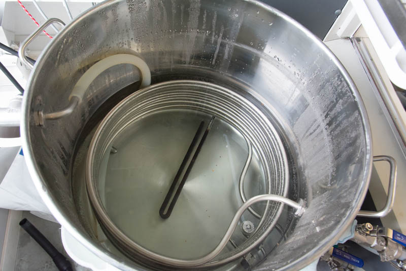
Hot Liquor Tun setup with whirlpool, heating element and HERMS coil.
Heat transfer as function of flow and temperature difference
The amount of heat that is transferred every second (power in Watts) can be calculated by multiplying the volume that is transferred, the temperature difference between coil input and output and the specific heat capacity of water. In formula form:
![\[ P = V \cdot \Delta T \cdot c_p\]](https://www.brewpi.com/wp-content/ql-cache/quicklatex.com-4c47370faa3be64a2f34552613effd4e_l3.png "Rendered by QuickLaTeX.com")
So to heat up your mash as quickly as possible, you want to maximize this equation.
Experiment setup
To find the ideal length, we needed to determine 2 things:
1. How much does each loop of the coil contribute to temperature rise?
It costs a lot of work and money to make multiple coils of different lengths, so we came up with an alternative: we decreased the amount of water in the HLT, submerging only a fraction of the coil. We assumed that only the submerged loops are contributing to the output temperature significantly.
Hot Liquor Tun water levels for each successive test.
2. How much friction does each loop add?
This one is a bit harder to test, so we took a more theoretical approach. We measured the flow rate twice, once bypassing the entire coil and once pumping through the coil. From the difference in flow rate, we calculated the friction factor of the entire coil. We used that value to calculate the friction that shorter coils would have.
The experiments
Flow rate
We measured the flow simply by filling a bucket with the return tube of the HLT, timing it and weighing the amount of water. The results were:
- 5.8 liters per minute with the coil
- 9.8 liters per minute without the coil.
Switching between with and without coil could be done by simply toggling a valve. Because it is fully automated Elco’s system has a lot of tubing, meaning there will be a lot more friction. In simpler setups with less tubing you will get higher flow. We correct for that later.
Flow calculations
There’s a lot of math in this section, feel free to skip it. What we did is measure the flow with and without the coil and from the difference we calculated the friction of the coil.
To calculate  (flow velocity in meters per second) we used the Bernoulli formula.
Bernoulli formula:
![\[(p_{1} + \frac{1}{2}\rho v_{1}^{2} + \rho g z_{1})-(p_{2} + \frac{1}{2}\rho v_{2}^{2} + \rho g z_{2})=f \frac{1}{2} \frac{L}{d} \rho v^{2} + K \frac{1}{2} \rho v^{2}\]](https://www.brewpi.com/wp-content/ql-cache/quicklatex.com-e0ce14a46d2e426b2249ecdba339026a_l3.png "Rendered by QuickLaTeX.com")
Without the coil, this formula simplifies to:
![\[p_{pump}= K \frac{1}{2} \rho v^{2}\]](https://www.brewpi.com/wp-content/ql-cache/quicklatex.com-69b58428f754f42b92186a8a38e6c4e9_l3.png "Rendered by QuickLaTeX.com")
This allows us to calculate K, our dimensionless loss factor for everything except the coil.
![\[K = \frac{2 \cdot p_{pump}}{\rho v^{2}}\]](https://www.brewpi.com/wp-content/ql-cache/quicklatex.com-dfd19e440a9a7b508651a5033c601974_l3.png "Rendered by QuickLaTeX.com")
Our pump pressure is known from manufacturer (4.5m head), and the density of water  at 60°C is 980
 ![\Big[ \frac{kg}{m^{3}} \Big]](https://www.brewpi.com/wp-content/ql-cache/quicklatex.com-16a67ca7bbd3e75019525cf0e273f391_l3.png "Rendered by QuickLaTeX.com")
Now that we have a good estimation for the loss factor K, the friction factor  of the the coil can be determined from the difference in flow velocity. The pressure of the pump does not change, so we can solve the following formula.
![\[p_{pump} = f \frac{1}{2} \frac{L}{d} \rho v_{1}^{2} + K \frac{1}{2} \rho v_{1}^{2} = K \frac{1}{2} \rho v_{2}^{2}\]](https://www.brewpi.com/wp-content/ql-cache/quicklatex.com-cae4405734be1674f073841b1382caa3_l3.png "Rendered by QuickLaTeX.com")
![\[f=K \cdot \frac{d}{L} \frac{v_{2}^{2}-v_{1}^{2}}{v_{1}^{2}}\]](https://www.brewpi.com/wp-content/ql-cache/quicklatex.com-8226cd25791b609d86de471d2a6e8b6b_l3.png "Rendered by QuickLaTeX.com")
Now that the friction factor of the coil is calculated it can be used to estimate the speed of the wort for different coil lengths.
![\[v = \sqrt{\frac{2 \cdot p_{pump}}{\rho (f \frac{L}{d}+K)}}\]](https://www.brewpi.com/wp-content/ql-cache/quicklatex.com-c5777b8d5bf3bdbf256527ac075a1bbb_l3.png "Rendered by QuickLaTeX.com")
We got a resulting friction factor of 0.0407, giving the following flow curves for a K of 30.
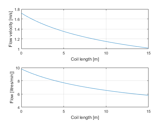
Volume flow and velocity for Elco’s system for various coil lengths
Elco’s system has a lot of tubing and valves, because it is fully automated. You can see the schematic of the entire system here:
Elco’s brewery with automated valves, interactive demo
To mimic our experiment in this setup, select the mash recirculation step. By toggling valve v6 we could bypass the coil.
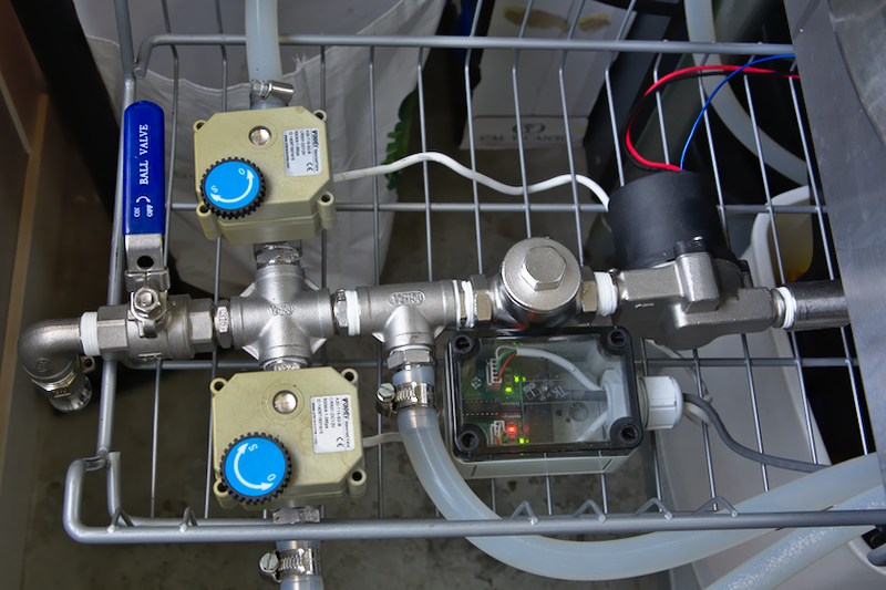
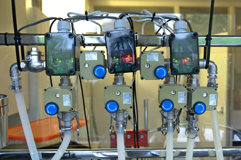
And here are some photos of the setup:
-
- With the temperature sensors inline with the coil, we could measure the coil in and output temperature.
-
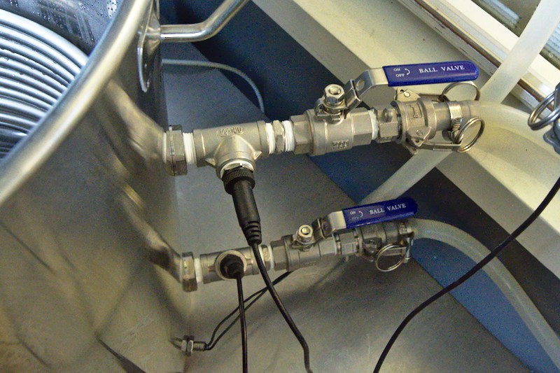
- This cluster pumps water from the HLT or water input to the HLT (top valve v1) or router cluster (bottom valve v2)
-
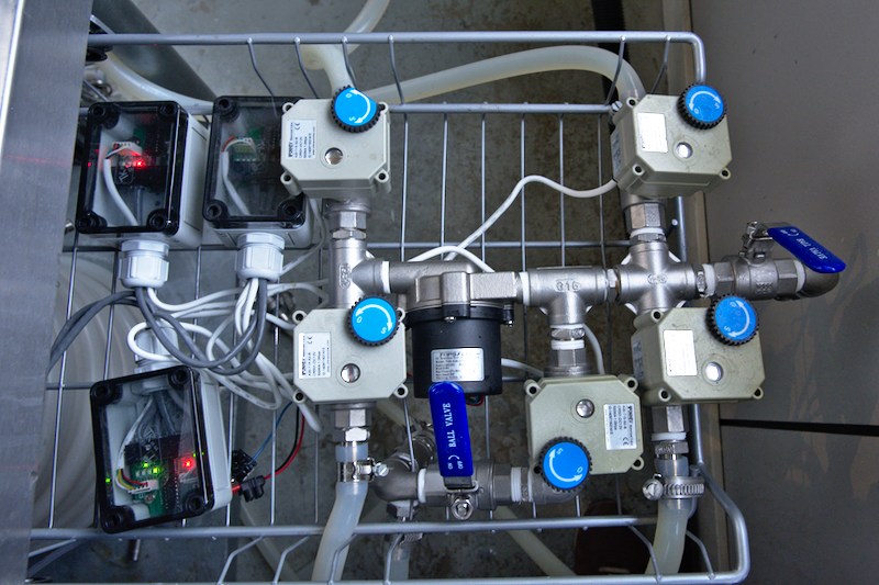
- This cluster gets water from the MT (top left v9) or BK (bottom left v10) and pumps it to the router cluster via the CFC (bottom right v12) and bypassing the CFC (top right v11) or drain (middle v13)
-
- This router cluster gets clean water from the left or wort from the right. The connections at the bottom are MT in (v3) coil out (v5) coil in (v7) or BK in (v8). By toggling v6, in between v5 and v7, we could bypass the HERMS coil.
-
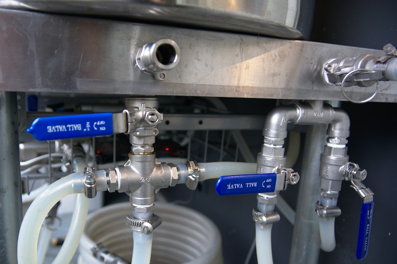
- This shows the water input on the right, with a valve for the water pump cluster and the CFC and a ‘to fermenter’ output on the left.
As you can see from the photos above, Elco’s setup has a lot of tubing and valves. This results in a lot of friction in the system, and therefore a high K factor. We think a K of 15 will be more representative of a typical homebrew setup.
A loss factor K of 15 will result in the following flow charts.
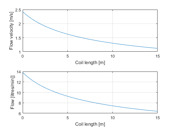
Volume flow and velocity for a more typical system with less tubing and valves
Coil efficiency vs. length
To measure the temperature distribution through the coil, we measured the output temperature of the coil for different water levels in the HLT. We measured:
- 1.5 loops submerged
- 3.5 loops submerged
- 5.5 loops submerged
- 7.5 loops submerged
- 9.5 loops submerged
- 11.5 loops submerged
For each water level in the HLT we recirculated the mash tun water through the HERMS coil to go from 55°C to 65°C, while trying to keep the HLT at 70 degrees. We measured:
- Coil in temperature
- Coil out temperature
- Mash tun in temperature
- Mash tun out temperature
- HLT temperature
Here you can see the measurements form having 11.5 loops submerged:
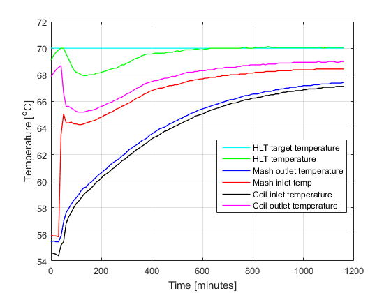
Raw data as recorded by the BrewPi brewing controller
For each measurement we started the HLT at 70 degrees and the MT at 55. We then closed valve v6 to switch from bypassing the coil to pumping through the coil.
After each run, we would discard some water from the MT, add some fresh cold water and make sure it was back at 55 degrees with the same volume for the next test.
We measured the input temperature difference (HLT – coil in) and the output temperature difference (coil out – coil in), so for each point in time we can calculate the efficiency  of the submerged section:
![\[\eta = 1 - \frac{\Delta T_{out}}{\Delta T_{in}}= 1- \frac{coil_{out}-coil_{in}}{HLT - coil_{in}}\]](https://www.brewpi.com/wp-content/ql-cache/quicklatex.com-587080f0db9d4a0d19f8f5c920244e6b_l3.png "Rendered by QuickLaTeX.com")
Each experiment would give us a set of points for the efficiency for a certain coil length. You can see these as a set of dots in the chart below. We only used the points for which the input temperature difference was between 4 and 8 degrees, which is the typical use case.
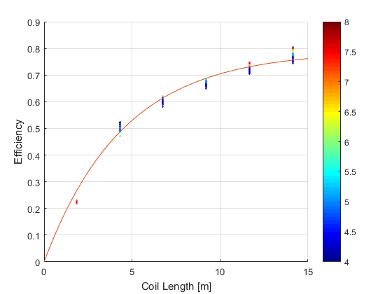
Efficiency of a HERMS coil for different coil lengths
We fitted a curve through these points, with the formula  where
where  is a time constant based on the lumped thermal capacity model. Our fitted curve has a time constant of 4.5,
  of 0.79, and
  is the time spent in the submerged part of the coil, which can be calculated form the flow velocity.
Now we can use this formula to calculate the coil output temperature for different lengths by calculating the time spent in coil () first and entering it in this formula.
Heat transfer analysis based on our experiments
Now that we have determined how coil length changes flow rate and efficiency, we can use the formulas to calculate how much heat will be transferred for each coil length and temperature difference. As you can see in the chart below, the curves are as expected: making the coil longer increases the efficiency, but after a certain point the loss in flow rate cancels out the higher output temperature.
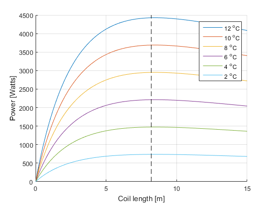
Power transferred to mash with different temperature differences between HLT and mash temperature
We have found 8.2 meters (dotted line) to be the most efficient length. The graph above is calculated with K = 15.
From the graph, you can also see that if your temperature difference is small, the power with which you heat your mash tun is low.
Recommendations for your own HERMS setup
During our experiments, we also found some quick improvements you can use to make your own mash go faster.
Exit the coil at the bottom
We did our experiments twice, once with the wort entering the coil at the top and leaving on the bottom and once the other way around. It turns out that having the wort in the HLT coil flow from top to bottom is more efficient that from bottom to top. This is because the water in the HLT is hotter closer to the element, even when there’s a whirlpool in the HLT. Our experiments found a 12% increase in efficiency when wort flowed from top to bottom.
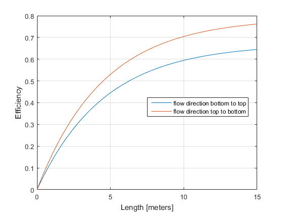
Two efficiency curves with changing flow direction within HERMS coil
Keep the temperature difference high
Because the heat transferred per second is  , to reach your mash temperature quickly, you will want to keep the temperature difference high. However, you don’t want to overshoot your target temperature. If you have a lot of water in the HLT, your HLT will continue to heat your mash if you keep pumping, even after you stop heating your HLT. All the heat that you put into your HLT will eventually distribute between your HLT and MT. A small example:
Let’s say you have 40L in your HLT and 40L in your mash tun. Your target temperature is 65 degrees and your mash is currently at 63 degrees. How high can you set your HLT to not overshoot? If you assume there are no temperature losses, the answer is 67 degrees. The equilibrium situation is that the HLT loses 2 degrees to the MT and both end up at 65:
![\[ \frac{63 \cdot 40 + 67 \cdot 40}{40 + 40} = 65\]](https://www.brewpi.com/wp-content/ql-cache/quicklatex.com-2edfd903110ad9da6688ec25bc962371_l3.png "Rendered by QuickLaTeX.com")
Now let’s take another look with only 10L in the HLT, still 40L in the mash tun. Now you can heat up the HLT to 73:
![\[ \frac{63 \cdot 40 + 73 \cdot 10}{40 + 10} = 65\]](https://www.brewpi.com/wp-content/ql-cache/quicklatex.com-c47428980f7a70c01acce306c395985a_l3.png "Rendered by QuickLaTeX.com")
With a 4 times smaller HLT, you can heat your mash 4 times quicker without overshooting. If you use BrewPi for mashing, you would set your Kp for the PID that manages the HLT setpoint to the  to automatically manage the HLT setpoint.
So our recommendation is:
- You can use a big kettle for your HLT, but don’t fill it up fully until you are heating your sparge water.
- Mount your HLT coil as close to the bottom as possible
- Use a low and wide HERMS coil if possible.
Whirlpool or stir your HLT
We measured the temperature response with and without recirculating our HLT water. This makes a big difference in the temperature exchange, as you can see from the graph below. Without stirring your HLT, the water around the coil will be a bit cooler, decreasing the output temperature.
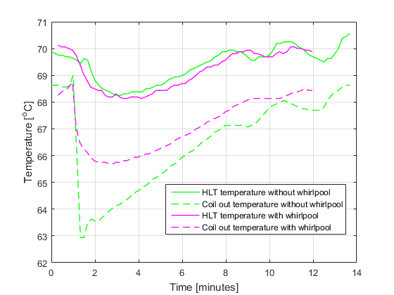
Whirlpool vs. no whirlpool in the HLT
Our new HERMS coils
We changed the HERMS coils we sell based on these experiments.
Our 30cm HERMS coil has been shorted from 12 windings to 8 windings. It is now 7.5m long instead of 11.3m.
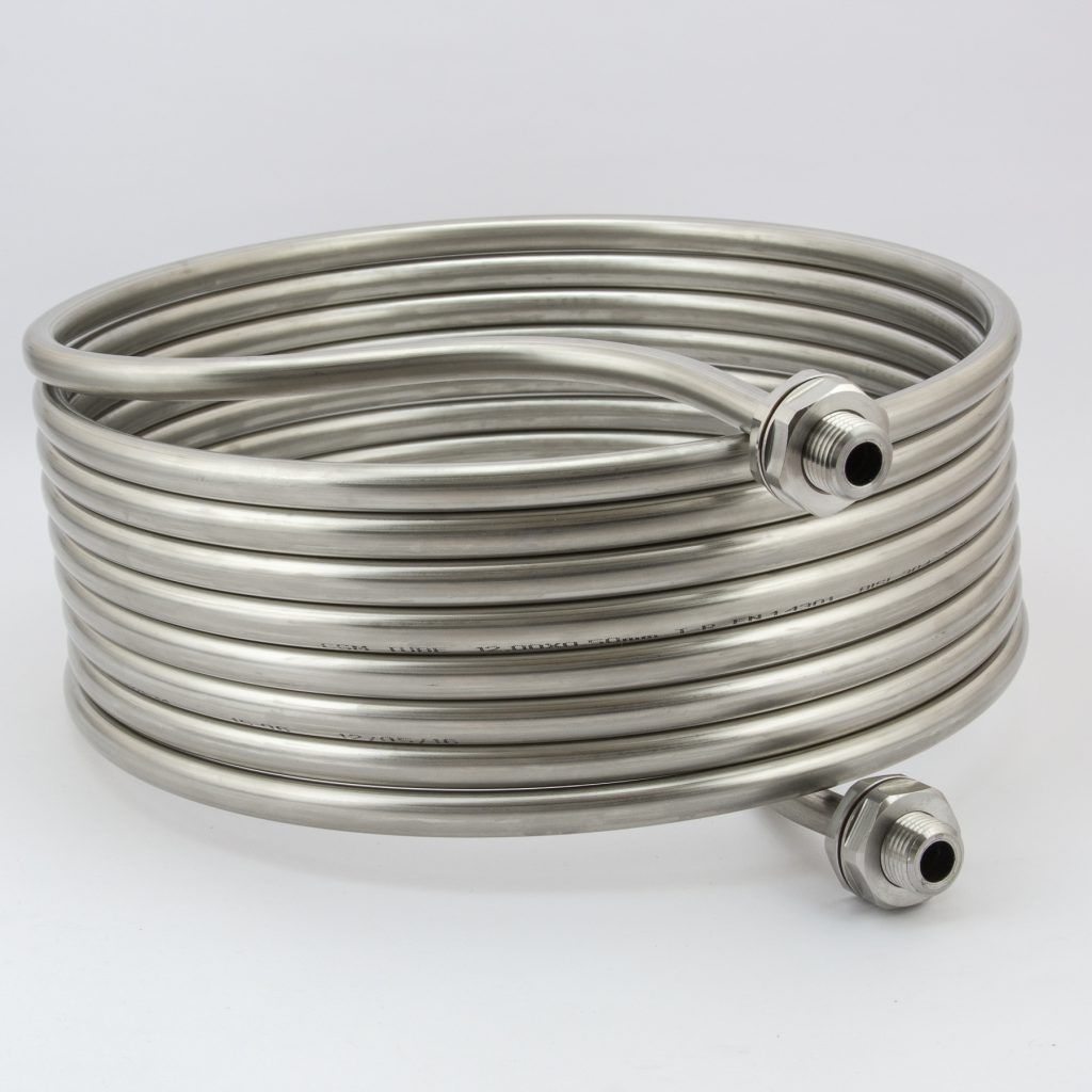
Our new 30cm HERMS coil
We are going to discontinue our 40cm HERMS coil, which was 15m long. The longer coil does not help with heat transfer. We have come up with an alternative though!
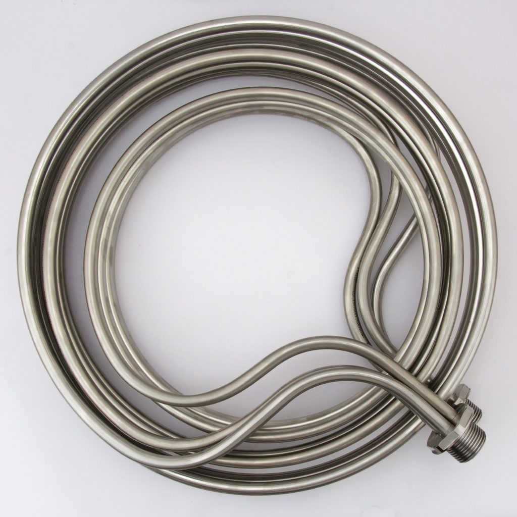
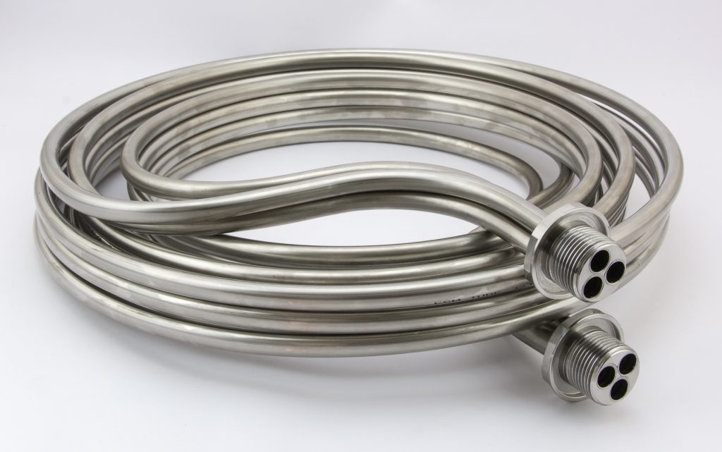
For big kettles, we have made a prototype of an entirely new design, suitable for big kettles and high power elements.
To maximize the heat transfer, we want to:
- Maximize the time the wort is in the coil, to increase the efficiency
- Reduce the friction of the coil
The only way to do both at once, is to increase the diameter of the coil. We chose to do this by having 3 coils in parallel, ending in one 1 inch fitting.
This design will have:
- A lower velocity and therefore less friction, because the flow velocity per coil is lower and the coil is shorter
- A lot of surface area
- A very low height, making it possible to have only very little water in the HLT to be able to work with bigger temperature differences.
The 30 cm HERMS coils are back in stock now. For the new 3-way parallel super awesome high flow coil, we only made a few prototypes. They’ll be available in about 4 weeks.
View all replies on our forum
25 more replies
Thanks for sharing your research and great work! I love when there’s science behind the claims. That 3-way coil looks so cool!
Great work Elco! Sorry on the possible OT but I saw some mentions of this on Reddit, and would like to know your opinion on how could these findings be applied to CFC (ie tube length, increasing flow rate, maximizing contact area etc.)? I was thinking of doing a similar experiment but it was too expensive to start with and there were too many variations in the mix (outer/inner diameter, convoluted copper vs regular one, the possibility of soldering wire in a spiral on the outside of inner tube for breaking of laminar flow, input water temperature etc). What interests me is which parameter would be the most beneficial one to the whole system (flow, area, temperature difference…).
I had some other experiences with the old larger discontinued herms coil, I first used the small one, and later on the larger one, and I saw a good difference in temp. I have always had circulation in the HLT, but when I actually used a bit of brain, I turned the outlet on the circulation in the opposite direction of the coil flow, that improved it a a lot as well
7 years ago I built a HERMS setup, and used it for a while. In 2014 I had to give the circuit controller back to my company (since it was on loan).
I feel compelled to finally get it all up and running again with an Arduino or raspberry pi.
Ultimately I hope to have as much automated as possible and press a single button to do everything.
My coil is 27 feet of 3/8 inch copper in a double coil configuration with each coil flowing in opposite directions.
Here is my Flickr photo album with detailed descriptions:

Some videos demonstrating the basic operation:
http://www.youtube.com/user/rubikbrewer#g/c/248E5283F7608CBA
I read through this and the engineer in me wanted to investigate some of the simplifications you made so I set out to optimize the HERMs coil analytically.
Over here most people use an AC pump produced by march or chuggar and because the “optimum” length is so dependent on the pump curve I wanted to be able to produce a family of curves for any pump and tubing set up. The example below is for the March 815-SS pump (one of the most common brewing pumps in the US) and assumes you have two 4ft lengths of 1/2" dia silicone hose with 90 elbows and cam lock fittings, a ball valve that is all the way open on your pump, 1/2" OD stainless steel tubing for the coil, and that you can maintain constant temp in your mash tun (i.e. you can provide the same heat you are extracting).
One thing the article neglected is that you don’t necessarily want higher HERMs outlet temps. Heat transfer is maximized when the temperature difference between the two materials is large. What that means is that the closer your wort temp in the HERMs coil gets to the HLT temp the less heat transfer into that fluid you get for the same area of heat exchanger. Additionally they neglect the fact that you don’t want the wort to get above 168F at all or you will start denaturing all of your amylases. On that note, you really want to do all you can to decrease the heat load on those amylases; therefore, you really want to have as small of a HERMs outlet temp differential as possible with a high flow rate.
The first run I just spit out the power vs. coil length but neglected the outlet temp and you get the graph below, which just says you want as big of a temperature difference between your mash temp and the HLT temp with a coil length of about 20ft.
The second run I killed each curve when the outlet temp increased above 165F (74C) which is why you see that strange feather shape on the left. The straight line back to zero is just a bug in how I plotted it, the curve should terminate at the top. What this says is that your maximum “enzyme safe” temp delta is 9C and at that delta T you want about 18ft of coil (yields a flow rate of ~3.5gpm). You can technically get a higher power system with the same pump if you have a very short coil but because that slope is so steep you run the risk of easily mis-estimating the head loss and not getting much power transfer at all or cooking your wort. To me, the risk is not worth the marginal power increase from the 9C delta set up. Also, that would need a very high flow rate and I think that would probably just result in a ton of grain bed settling, restricting your flow and then cooking your wort.
SO,
Lessons learned:
-You don’t need the expensive 50+ foot coils everyone is trying to sell you
-Next time I see an article about brewing that relates to engineering I should probably just not read it for my own sake
“